PULSE - One-shot pulse delay and stretch
A PULSE block produces configurable width output pulses with an optional delay based on its parameters. If WIDTH is non-zero, the output pulse width will be the specified amount. If DELAY is non-zero, the pulse train will be delayed by that amount. If both are non-zero, the pulses are stretched and delayed as long as the resulting output would still contain the same number of distinct pulses. If this is not the case, then the PERR signal is raised, and the MISSED_CNT counter is incremented. Change of any parameter causes the block to be reset.
Fields
| Name | Type | Description |
|---|---|---|
| DELAY | time | Output pulse delay (0 for no delay) |
| WIDTH | time | Output pulse width (0 for input pulse width) |
| ENABLE | bit_mux | Reset on falling edge, enable on rising |
| TRIG | bit_mux | Input pulse train |
| OUT | bit_out | Output pulse train |
| QUEUED | read uint 1023 | Length of the delay queue |
| DROPPED | read | Number of pulses not produced because of an ERR condition |
| TRIG_EDGE | param enum | INP trigger edge
0 Rising
1 Falling
2 Either
|
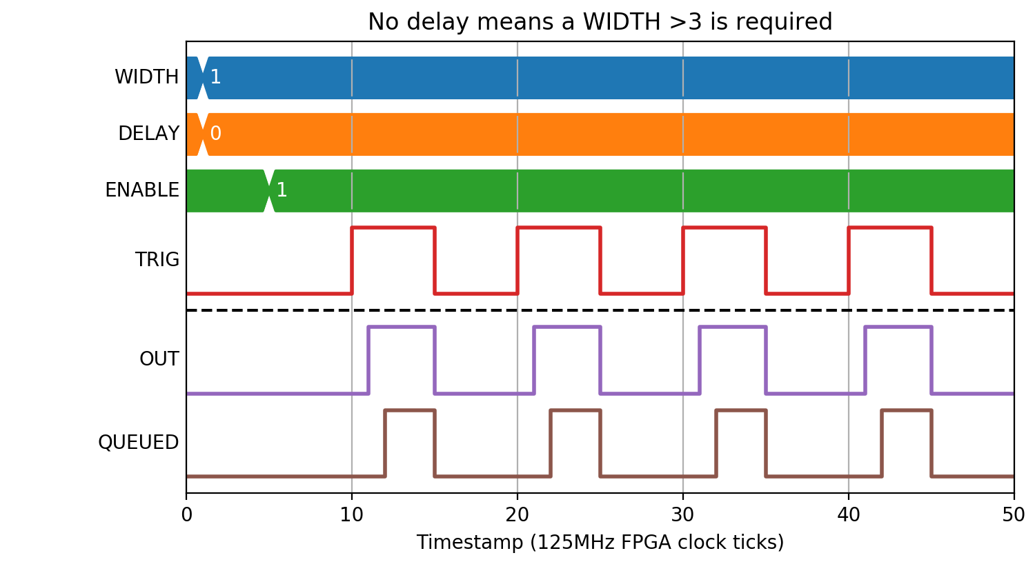
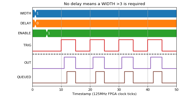
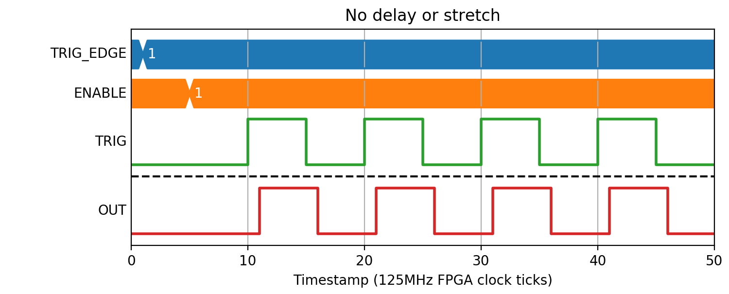
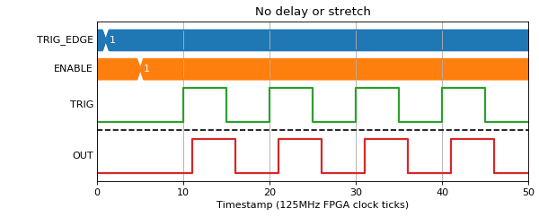
Zero Delay
If DELAY=0, then the INP pulse will be stretched with only the propagation delay of the block (1 clock tick). WIDTH must be at least 4, and any value given below is defaulted to four.
(Source code, png, hires.png, pdf)
(Source code, png, hires.png, pdf)
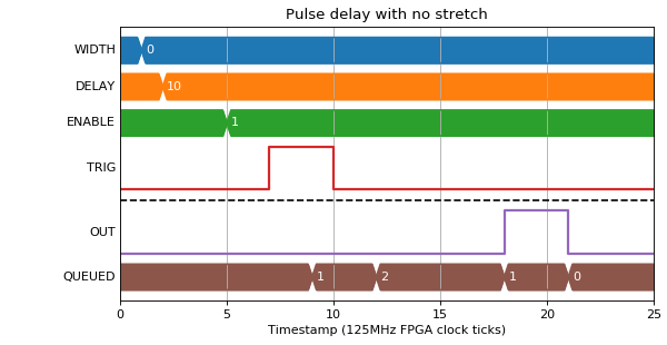
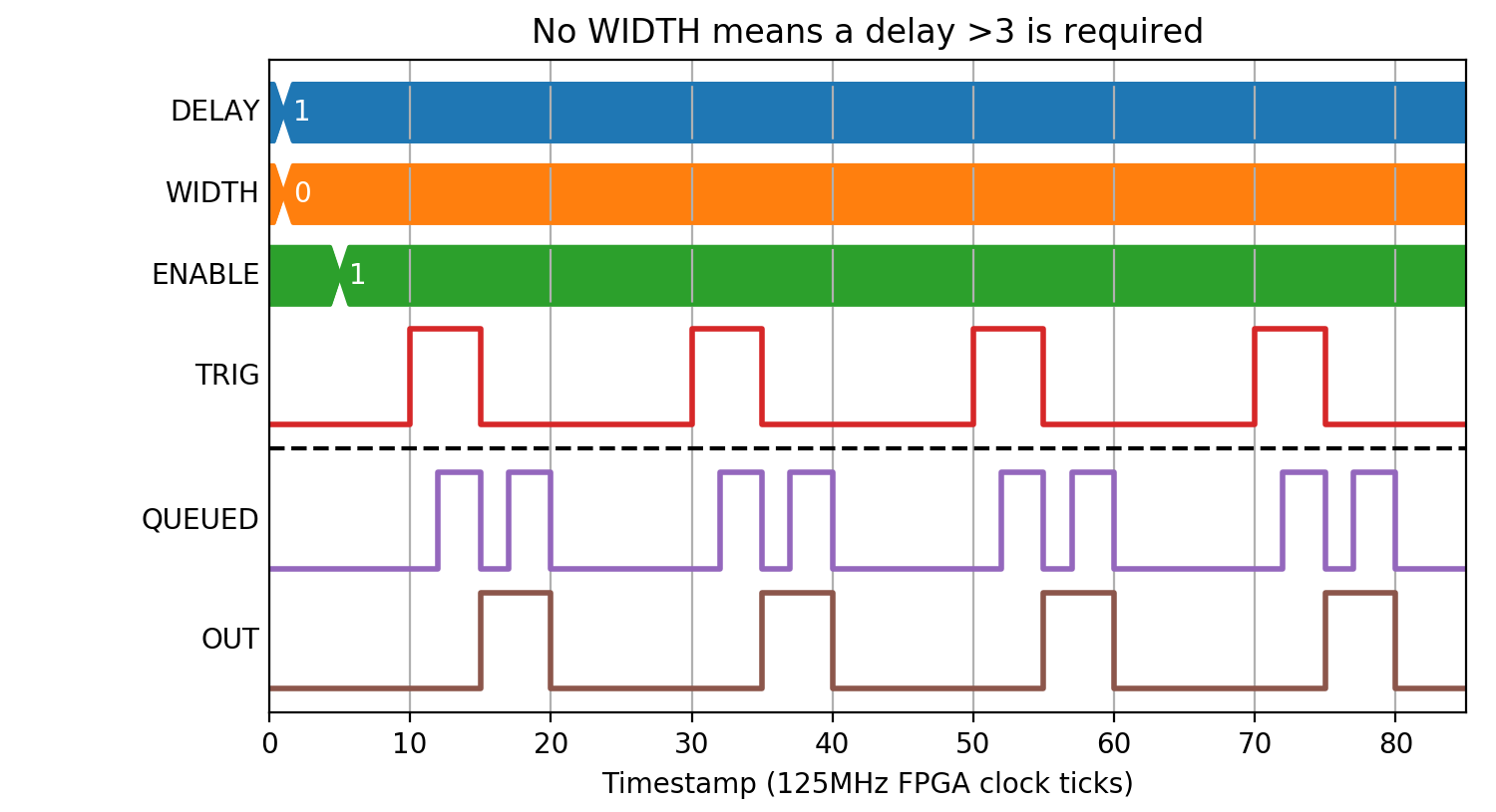
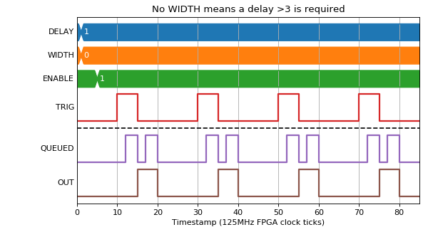
Zero Width
If WIDTH=0, then the INP pulse width will be used. DELAY must be >3 clock ticks, any lower inputted values will be defaulted to four.
(Source code, png, hires.png, pdf)
(Source code, png, hires.png, pdf)
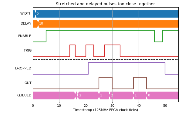
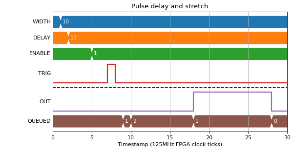
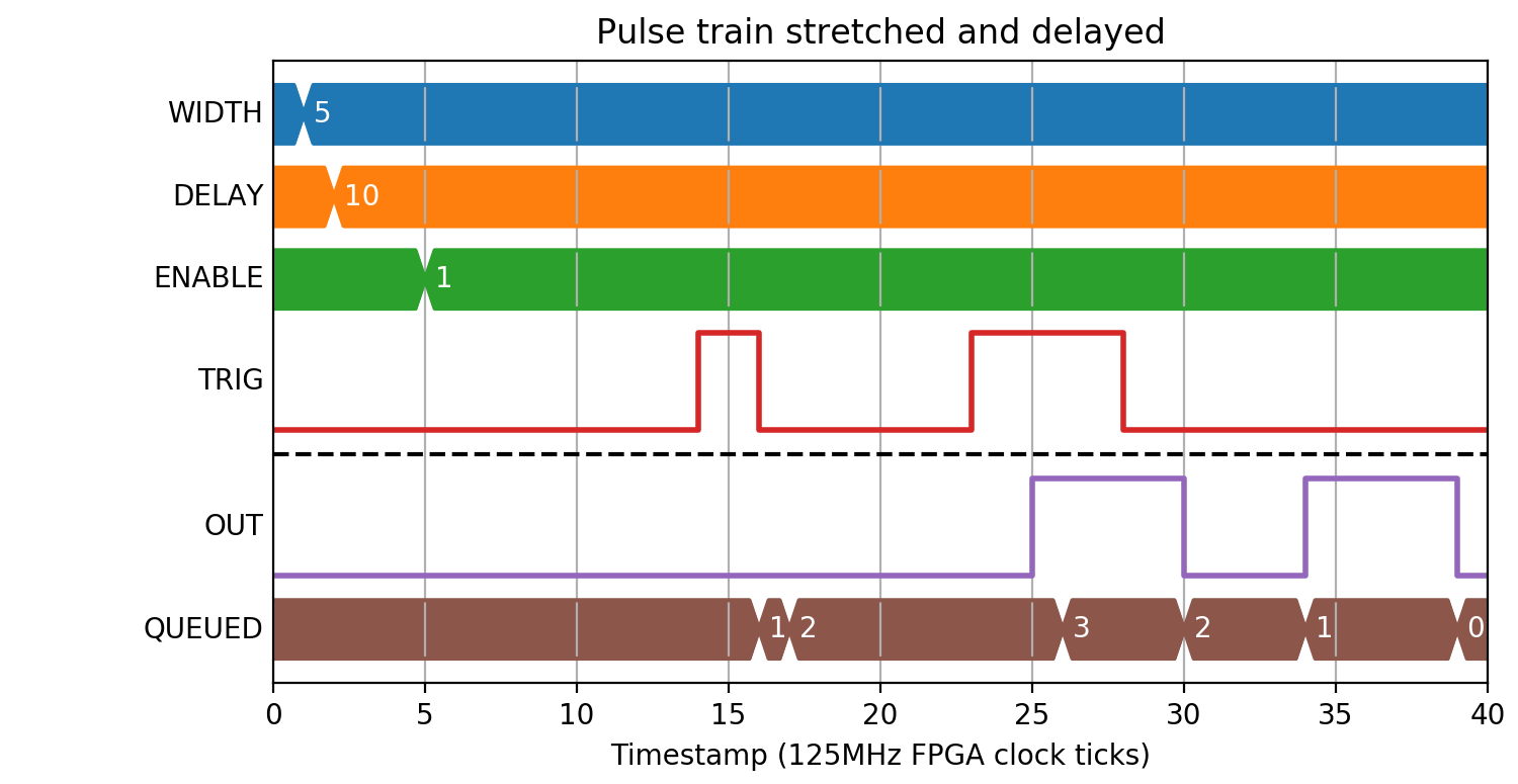
Width and Delay
In this mode, pulses are placed onto an output queue, so a number of restrictions apply:
- There must not be more than 1023 pulses on the output queue
- WIDTH must be >3 clock ticks
- There must be >3 clock ticks where output is 0 between pulses. This means that WIDTH < T - 3 where T is the minimum INP pulse period
(Source code, png, hires.png, pdf)

(Source code, png, hires.png, pdf)

(Source code, png, hires.png, pdf)
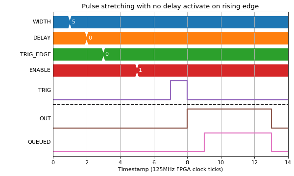
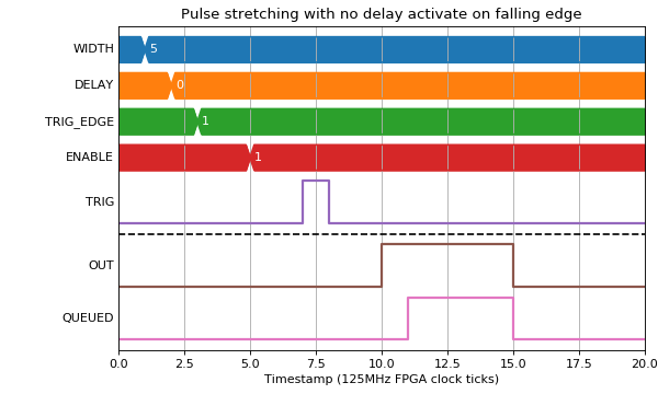
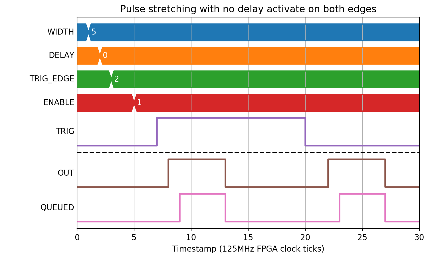
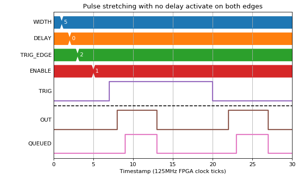
Different Edge Activation
When there is a width specified, it is possible to also specify which edge of the input pulse activates the output.
(Source code, png, hires.png, pdf)
(Source code, png, hires.png, pdf)
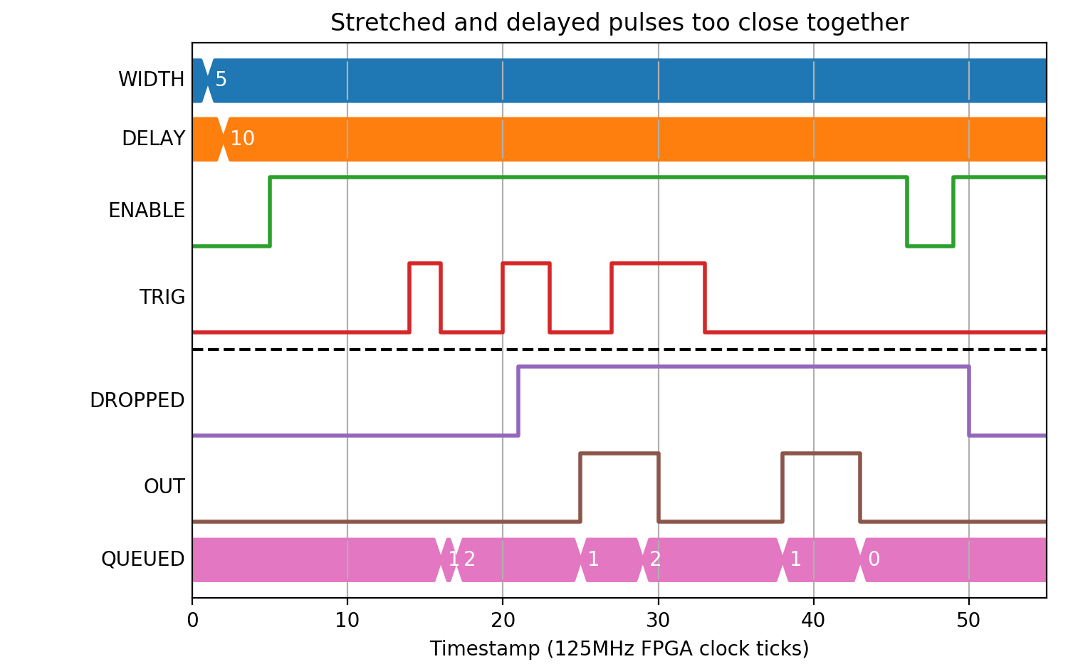
Pulse period error
The following example shows what happens when the period between pulses is too short.
(Source code, png, hires.png, pdf)