COUNTER [x8]
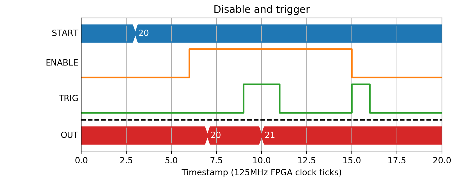
Each counter block, when enabled, can count up/down with user-defined step value on the rising edge on input trigger. The counters can also be initialised to a user-defined START value.
Parameters
| Name | Dir | Type | Description |
|---|---|---|---|
| START | W | UInt32 | Counter start value |
| STEP | W | UInt32 | Up/Down step value |
| ENABLE | In | Bit | Halt on falling edge, reset and enable on rising |
| TRIG | In | Bit | Rising edge ticks the counter up/down by STEP |
| DIR | In | Bit | Up/Down direction (0 = Up, 1 = Down) |
| CARRY | Out | Bit | Internal counter overflow status |
| OUT | Out | Pos | Current counter value |
Counting pulses
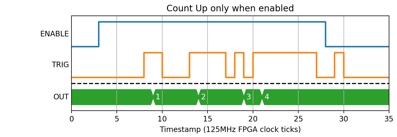
The most common use of a counter block is when you would like to track the number of rising edges received while enabled:
(Source code, png, hires.png, pdf)

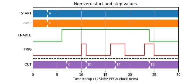
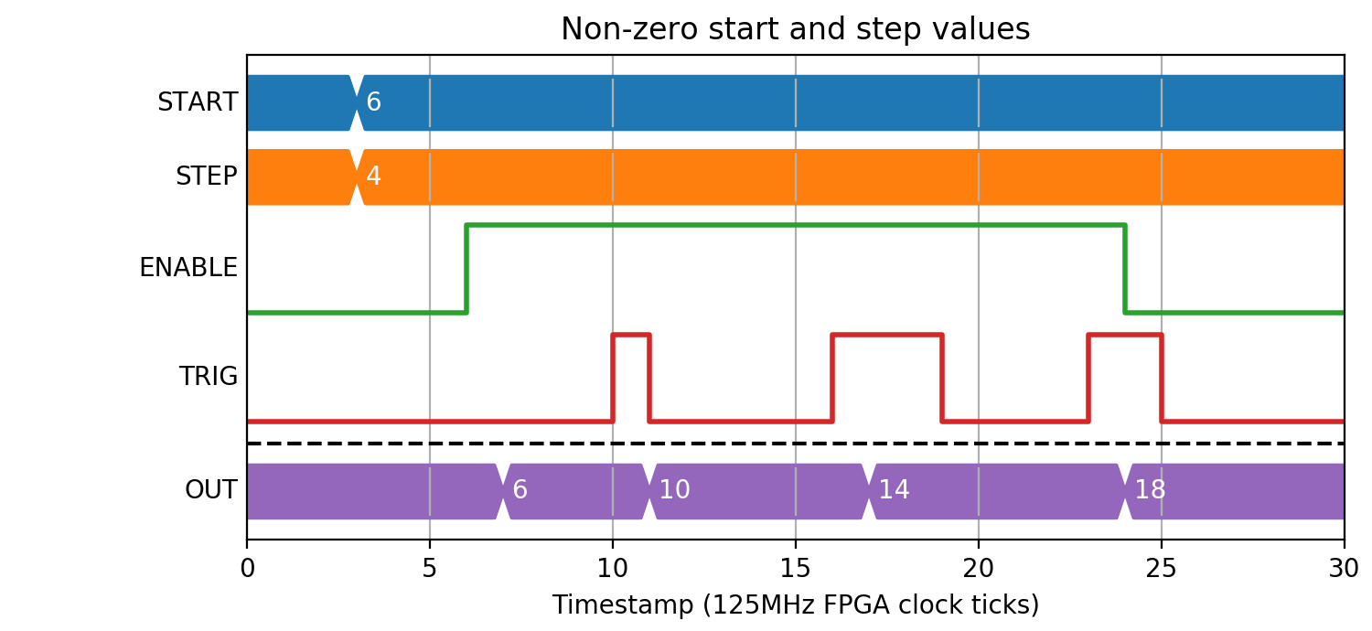
You can also set the start value to be loaded on enable, and step up by a number other than one:
(Source code, png, hires.png, pdf)

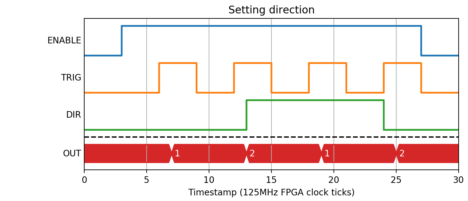
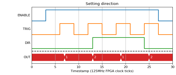
You can also set the direction that a pulse should apply step, so it becomes an up/down counter. The direction is sampled on the same clock tick as the pulse rising edge:
(Source code, png, hires.png, pdf)
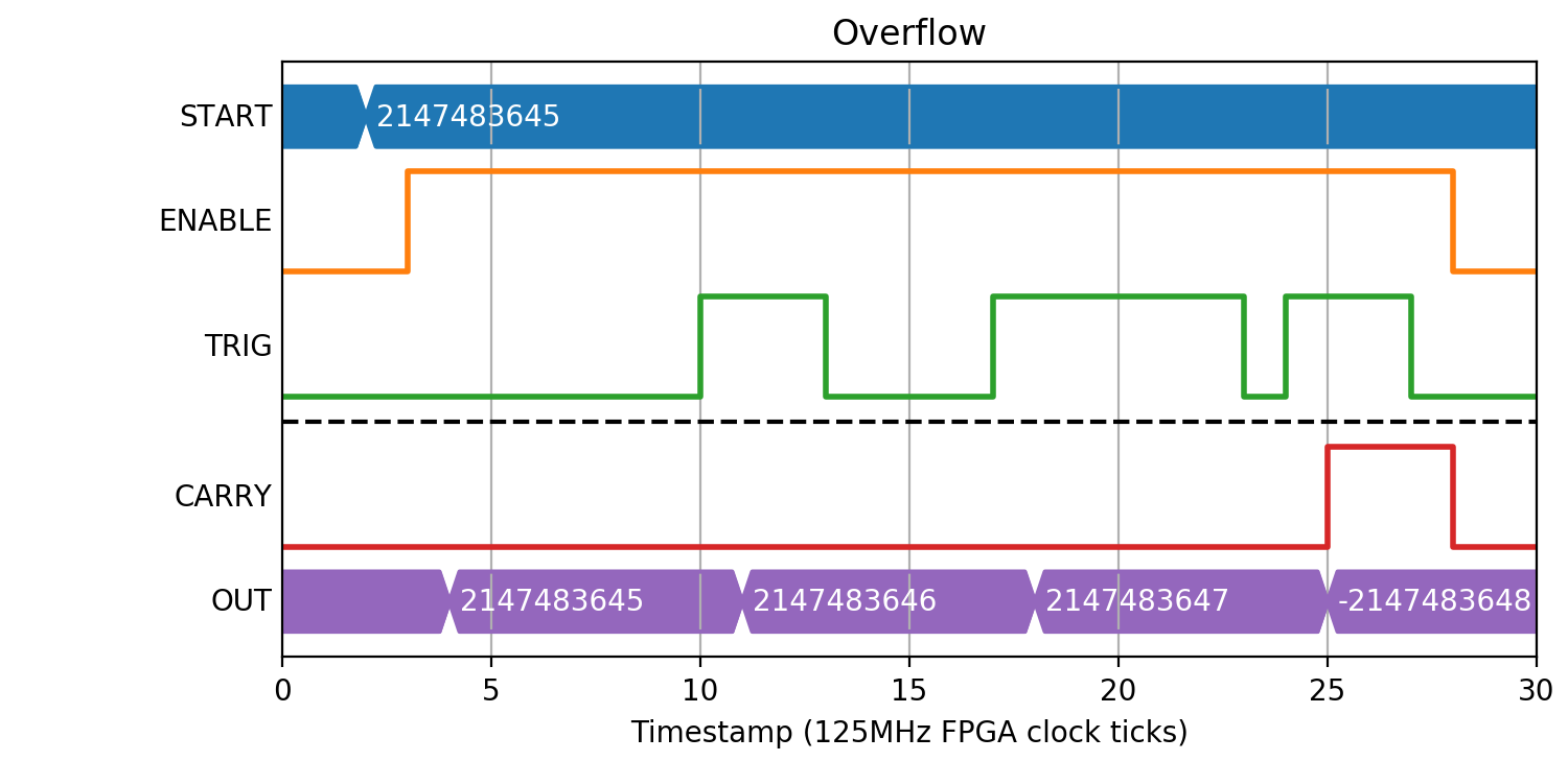
Rollover
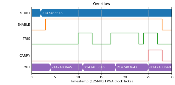
If the count goes higher than the max value for an int32 (2147483647) the CARRY output gets set high and the counter rolls. The CARRY output stays high for as long as the trigger input stays high.
(Source code, png, hires.png, pdf)

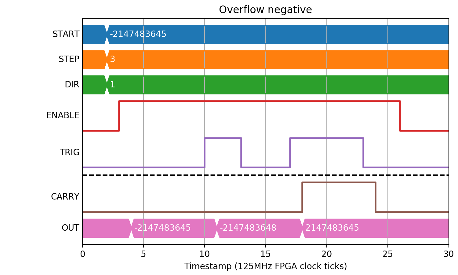
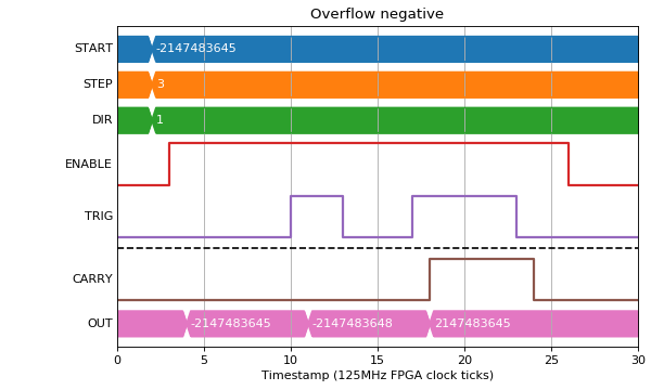
A similar thing happens for a negative overflow:
(Source code, png, hires.png, pdf)
Edge cases
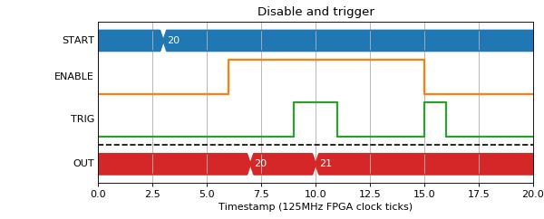
If the Enable input goes low at the same time as a trigger, there will be no output value on the next clock tick.
(Source code, png, hires.png, pdf)

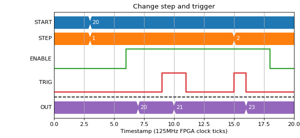
If the step size is changed at the same time as a trigger input rising edge, the output value for that trigger will be the new step size.
(Source code, png, hires.png, pdf)