SRGATE - Set Reset Gate
An SRGATE block produces either a high (SET) or low (RST) output. It has configurable inputs and an option to force its output independently. Both Set and Rst inputs can be selected from bit bus, and the active-edge of its inputs is configurable. An enable signal allows the block to ignore its inputs.
Parameters
| Name | Dir | Type | Description |
|---|---|---|---|
| WHEN_DISABLED | R/W | Enum | What to do with the output when Enable is low
0 Set output low
1 Set output high
2 Keep current output
|
| SET_EDGE | R/W | Enum | 0 - Sets the output to 1 on rising edge
1 - Sets the output to 1 on falling edge
2 - Sets the output to 1 on either edge
|
| RESET_EDGE | R/W | Enum | 0 - Resets the output on rising edge
1 - Resets the output on falling edge
2 - Resets the output on either edge
|
| FORCE_RESET | W | Action | Reset output to 0 |
| FORCE_SET | W | Action | Set output to 0 |
| ENABLE | In | Bit | Whether to listen to SET/RST events |
| SET | In | Bit | A falling/rising edge sets the output to 1 |
| RESET | In | Bit | A falling/rising edge resets the output to 0 |
| OUT | Out | Bit | Output value |
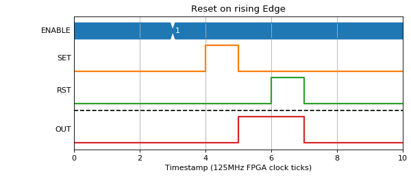
Normal conditions
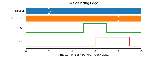
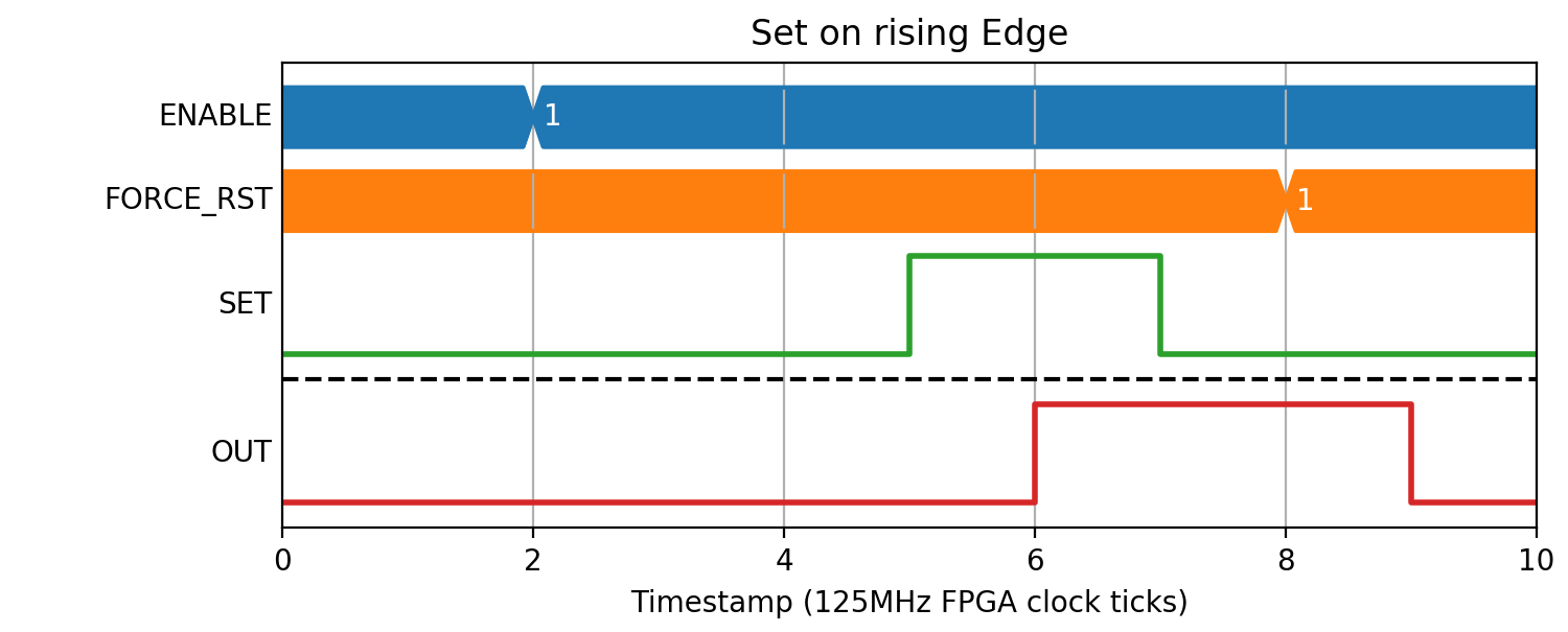
The normal behaviour is to set the output OUT on the configured edge of the SET or RESET input.
(Source code, png, hires.png, pdf)

(Source code, png, hires.png, pdf)

(Source code, png, hires.png, pdf)

(Source code, png, hires.png, pdf)
(Source code, png, hires.png, pdf)
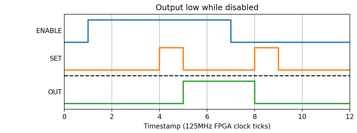
Disabling the block
The default behaviour is to force the block output low when disabled, ignoring any SET/RST events:
(Source code, png, hires.png, pdf)

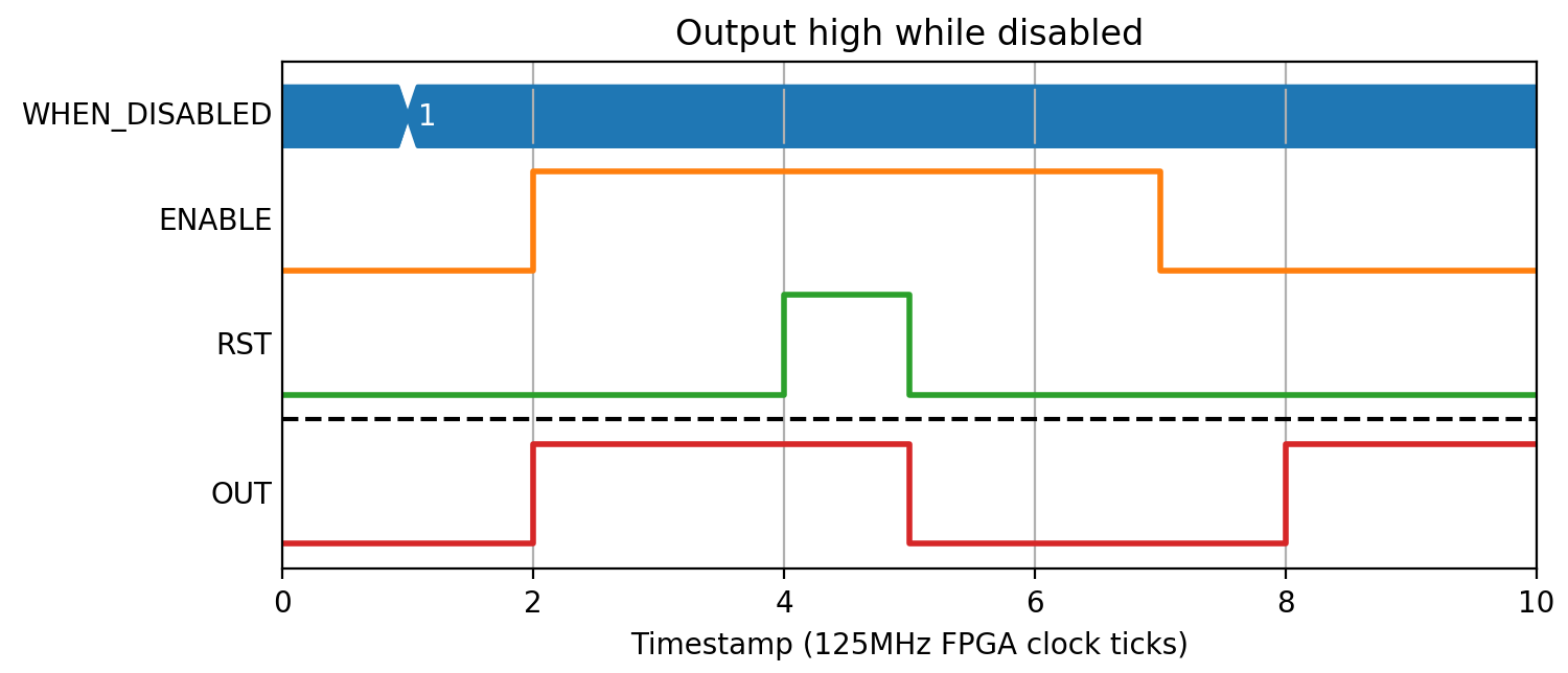
The disabled value can also be set high:
(Source code, png, hires.png, pdf)

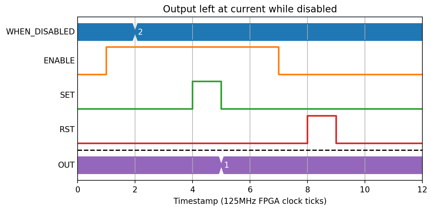
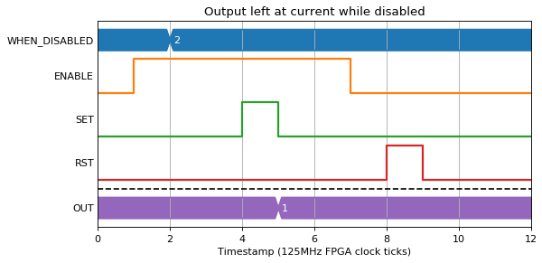
Or left at its current value:
(Source code, png, hires.png, pdf)
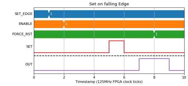
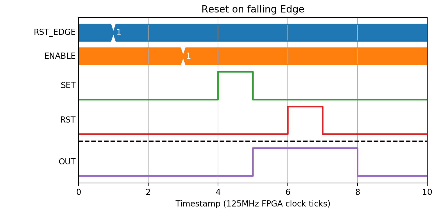
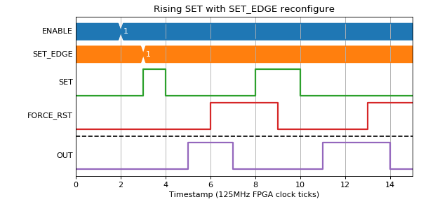
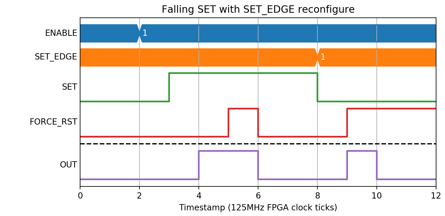
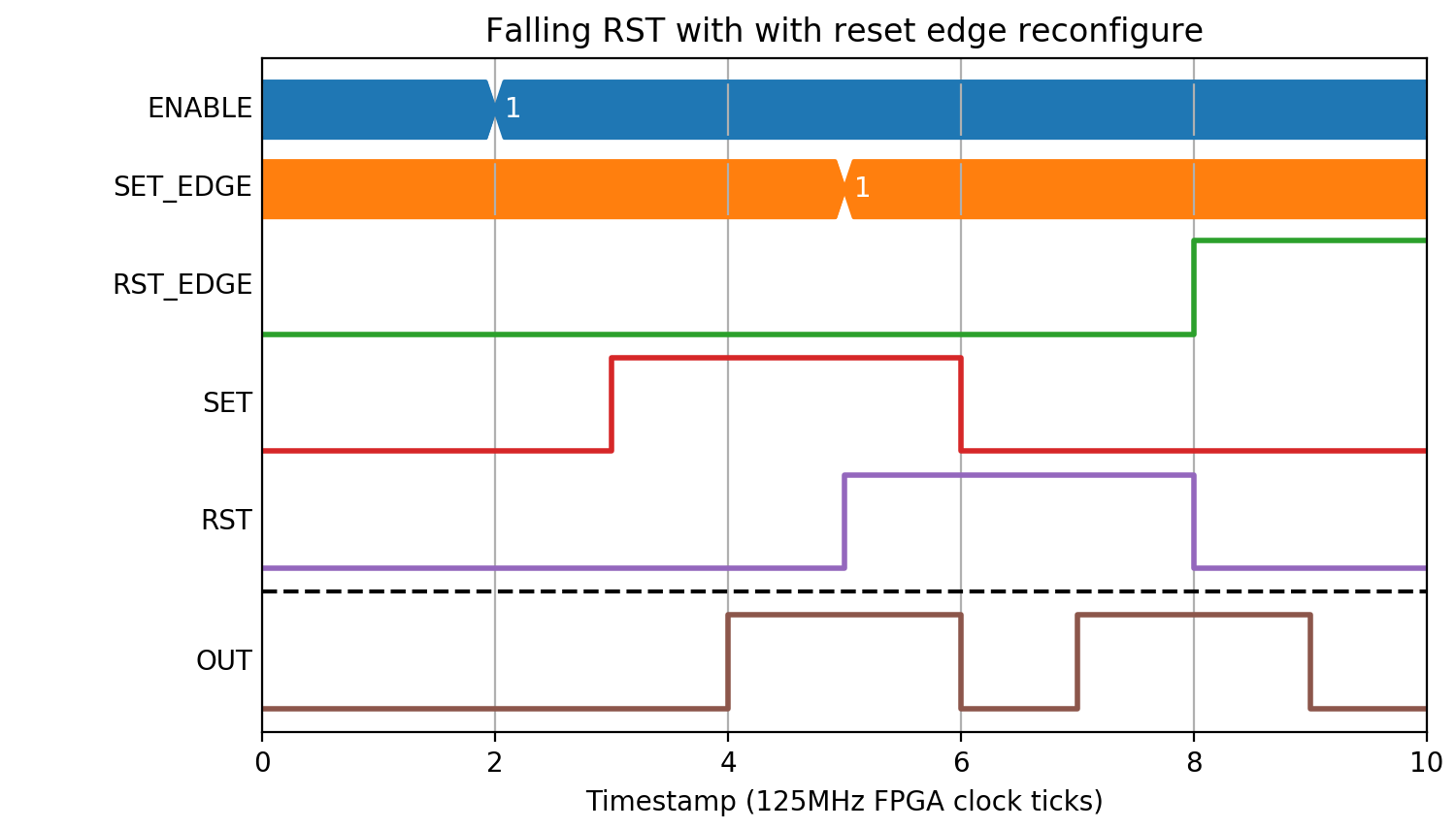
Active edge configure conditions
if the active edge is ‘rising’ then reset to ‘falling’ at the same time as a rising edge on the SET input, the block will ignore the rising edge and set the output OUT on the falling edge of the SET input.
(Source code, png, hires.png, pdf)
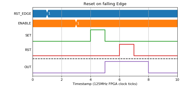
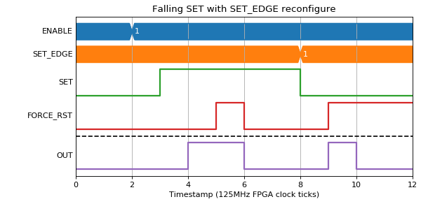
If the active edge changes to ‘falling’ at the same time as a falling edge on the SET input, the output OUT will be set following this.
(Source code, png, hires.png, pdf)
(Source code, png, hires.png, pdf)

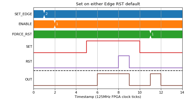
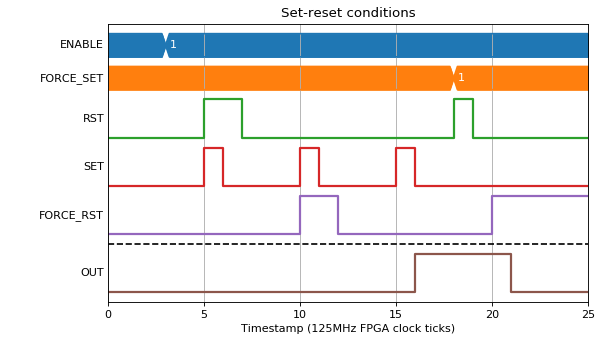
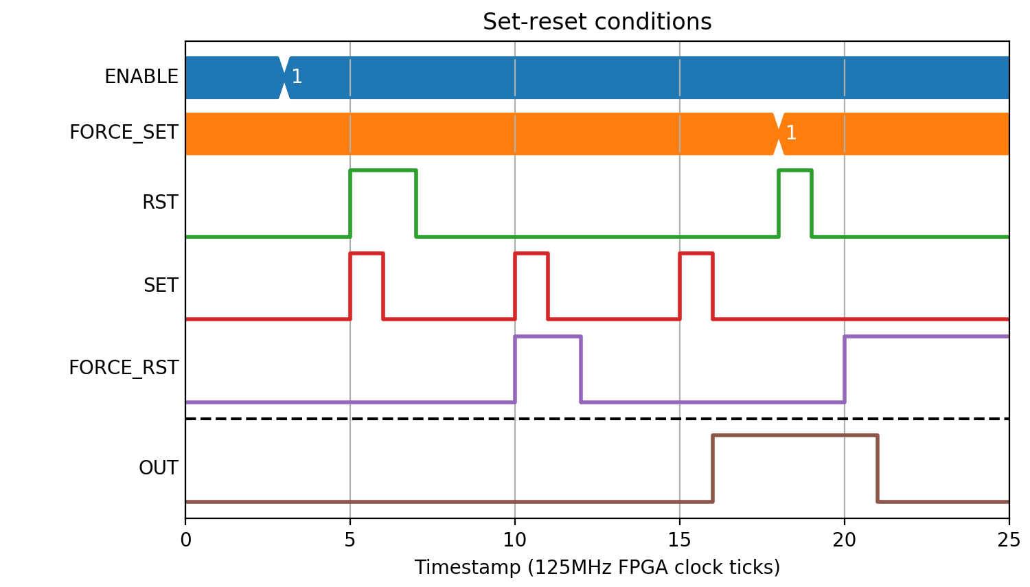
Set-reset conditions
When determining the output if two values are set simultaneously, FORCE_SET and FORCE_RESET registers take priority over the input bus, and reset takes priority over set.
(Source code, png, hires.png, pdf)
