PULSE - One-shot pulse delay and stretch [x4]
A PULSE block produces configurable width output pulses with an optional delay based on its parameters. If WIDTH is non-zero, the output pulse width will be the specified amount. If DELAY is non-zero, the pulse train will be delayed by that amount. If both are non-zero, the pulses are stretched and delayed as long as the resulting output would still contain the same number of distinct pulses. If this is not the case, then the PERR signal is raised, and the MISSED_CNT counter is incremented. Change of any parameter causes the block to be reset.
Parameters
| Name | Dir | Type | Description |
|---|---|---|---|
| DELAY | R/W | Time | Output pulse delay. Must be either 0 (no delay) or >4 clock ticks |
| WIDTH | R/W | Time | Output pulse width. If 0, the width of the input pulse is used |
| FORCE_RESET | W | Action | Reset QUEUE and ERR outputs |
| INP | In | Bit | Input pulse train |
| RESET | In | Bit | On edge defined by EDGE, reset QUEUE and ERR outputs |
| EDGE | R/W | Enum | 0 - rising edgee
1 - falling edg
2 - either edge
|
| OUT | Out | Bit | Output pulse train |
| PERR | Out | Bit | Error output. If a pulse could not be generated This will be set to 1 until the block is RESET |
| ERR_OVERFLOW | R | Bit | Indicates a missed pulse was due to overflow of the internal queue. If DELAY is non-zero then up to 1023 pulse edges can be queued waiting for output. |
| ERR_PERIOD | R | Bit | If producing a pulse would cause it to overlap with the previous pulse (WIDTH > time between pulses), then this flag is set. |
| QUEUE | R | UInt32 | Length of the delay queue in range [0..1023] |
| MISSED_CNT | R | UInt32 | Number of pulses that have not been produced because of an ERR condition. Will only be non-zero when PERR is 1 |
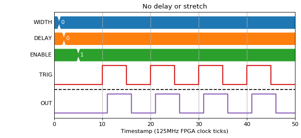
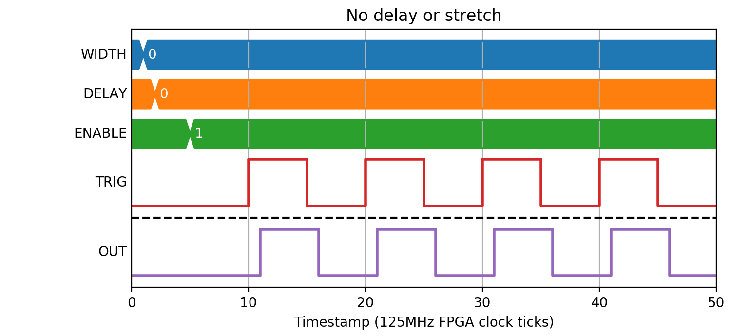
Zero Delay
If DELAY=0, then the INP pulse will be stretched with only the propogation delay of the block (1 clock tick). WIDTH may take any value, as long as input pulses are spaced enough to allow stretched pulses to be produced.
(Source code, png, hires.png, pdf)

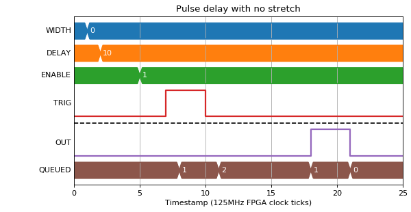
Zero Width
If WIDTH=0, then the INP pulse width will be used. DELAY must be >4 clock ticks.
(Source code, png, hires.png, pdf)

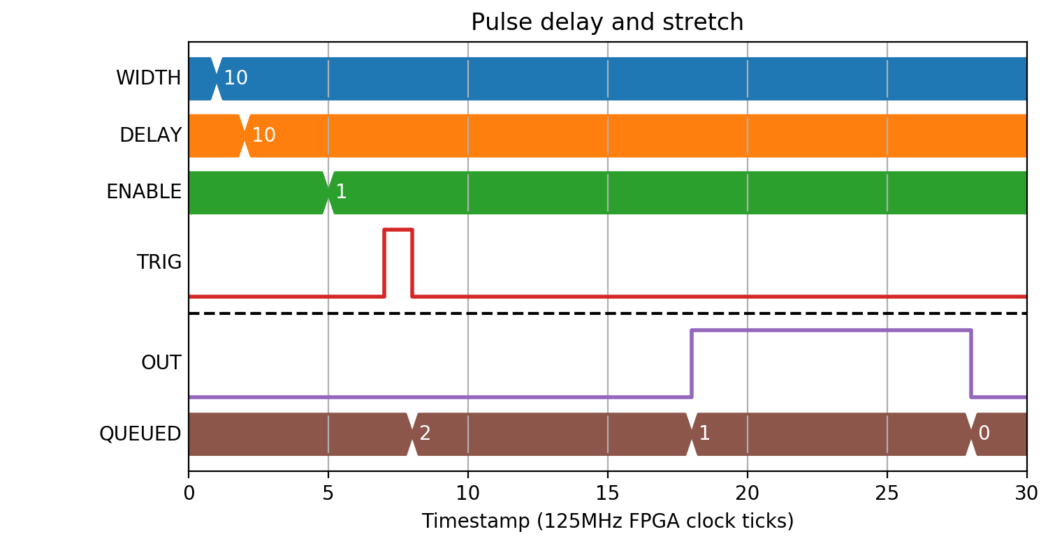
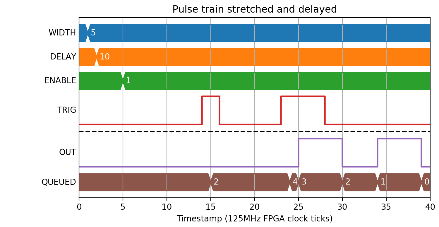
Width and Delay
In this mode, pulses are placed onto an output queue, so a number of restrictions apply:
- There must not be more than 1023 pulses on the output queue
- WIDTH must be >3 clock ticks
- There must be >3 clock ticks where output is 0 between pulses. This means that WIDTH < T - 3 where T is the minimum INP pulse period
(Source code, png, hires.png, pdf)

(Source code, png, hires.png, pdf)

(Source code, png, hires.png, pdf)

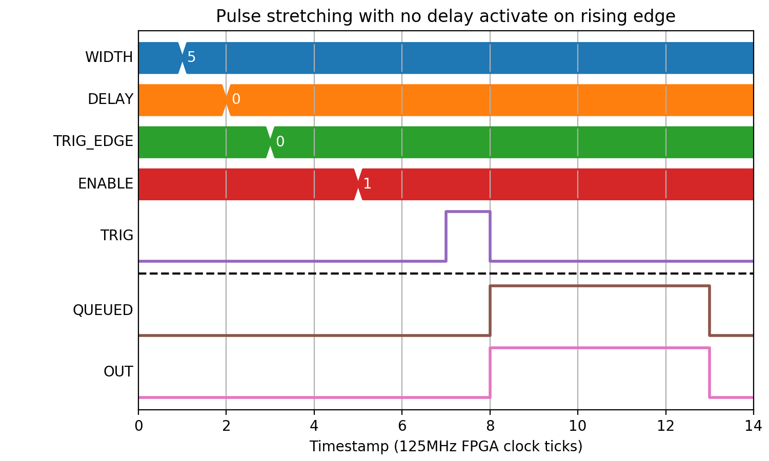
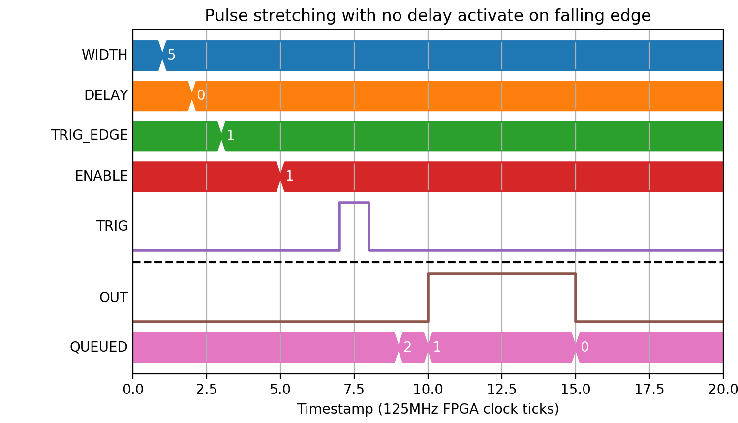
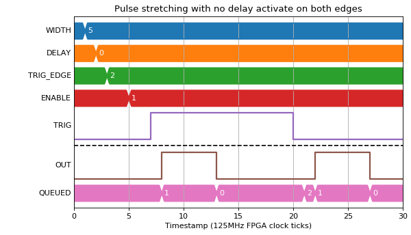
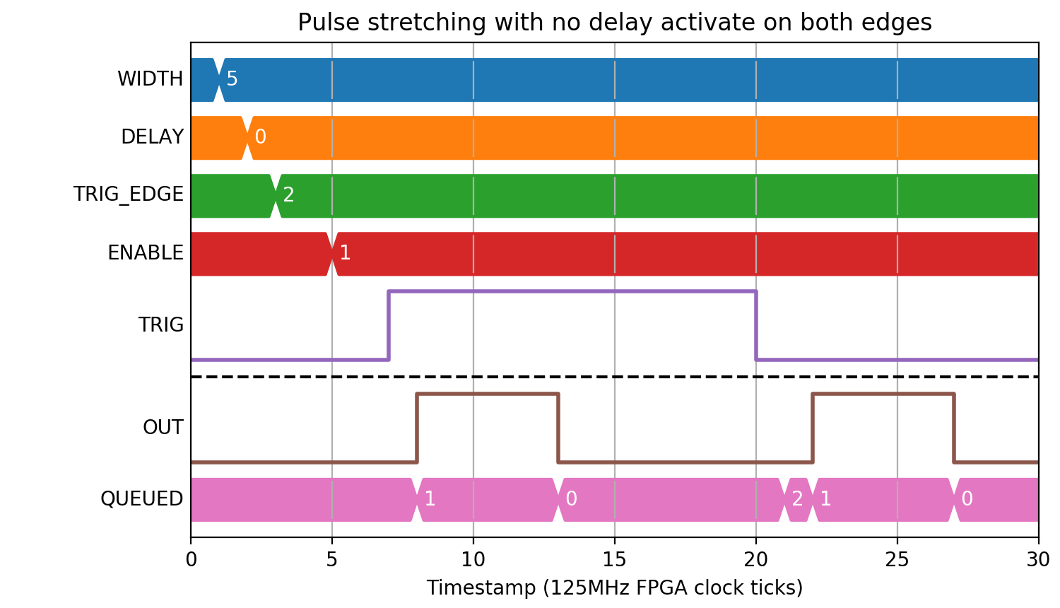
Different Edge Activation
When there is a width specified, it is possible to also specify which edge of the input pulse activates the output.
(Source code, png, hires.png, pdf)

(Source code, png, hires.png, pdf)
(Source code, png, hires.png, pdf)

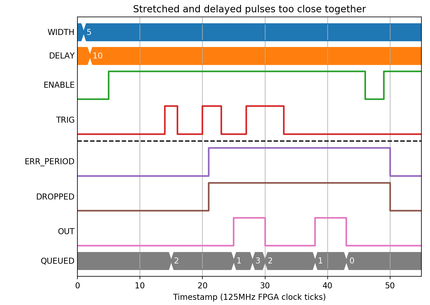
Pulse period error
The following example shows what happens when the period between pulses is too short.
(Source code, png, hires.png, pdf)
